-
Missing events in dynamic calculations
Events are sometimes lost when dynamic calculations (i.e. including amplitudes) are done.
Sample the wavefront denser in Functions;Trace Wavefronts... -> Set Technical Parameters... -
Tracing does not start
Tracing sometimes fails due to too many points in the exploding source wavefront.
Sample the wavefront sparser in Functions -> Trace Wavefronts... -> Set Technical Parameters... -
-
The number of events allocated is too small
The "Maximum and Average # Events In Each Receiver" in the dialog "Set Event Attributes" is the number of events for all the ray codes together. If the number of ray codes is large, it may lead to a stop in the modelling when the total number of events allocated is reached.
Increase the "Maximum and Average # Events In Each Receiver" so that all events for all ray codes may be stored in memory. -
The Common Shot Wavefront Tracer crashes during the loading of a model
The Common Shot Wavefront Tracer crashes during the loading of a model, if a model already has been loaded which contains layers that share property grids with other layers.
Exit the Common Shot Wavefront Tracer and read the model. -
How are the angles defined in NORSAR-3D (e.g. theta & phi in the Wavefront Tracer?)
-
How is the seismic amplitude defined and which parts can be extracted?
Amplitudes in NORSAR-3D (PDF)
-
Can you explain the accuracy parameter under the technical parameter menu? What quantity is more or less accurate and by how much?
During tracing of ray segments connecting two wavefronts, we obtain an estimate of the square of maximum error in distance per second traced ray. This quantity, ERR, has the unit of velocity squared (km²/s²). According to whether the user selects accuracy "Low", "Moderate", "High", or "Very High" the quantity ERR will be kept between predefined limits. The current limits set in the program are the following:
- Low:
- ERR must be <= 1.0e-2
- Moderate:
- ERR must be <= 2.5e-3
- High:
- ERR must be <= 1.0e-4
- Very High:
- ERR must be <= 1.0e-6
For velocity fields including relatively sharp contrasts it is recommended to use High or Very High to ensure that the ray tracer handles such contrasts properly. For smooth velocity fields, Moderate or Low may often be sufficient.
- Low:
-
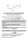
What is the definition of the P and Q matrices in NORSAR-3D?
Our calculation of Q and P matrices of size 2 x 2 is based on a Hamiltonian function corresponding to traveltime as the variable along the ray (see, e.g., Cerveny, 2001). For isotropic media, the differential equations that we use are the following:
dQ/dt = v^2 P
dP/dt = -v^{-1}VQ
ds/dt = v
with the initializations
Q(0)=0
P(0)=I .
The matrices Q and P refer to a local ray-centered system which is continuously rotated along the ray (Popov and Psencik, 1979). This means that we also need an additional differential equation describing the change of rotation of the basis vectors of the system. For details, see Cerveny's books from 1985, 2001 or his earlier work on the subject.
In the equations above, v is the velocity in the current point on the ray, and V is a 2 x 2 matrix containing second derivatives of velocity with respect to local ray-centered coordinates. The "0" and "I" denote, respectively, the zero matrix and identy matrix of size 2 x 2. -
Plotted rays do not hit the receiver
NORSAR-3D uses the Wavefront construction method to model the seismic events (see chapter 2.4 in the User's Guide) The wavefront construction method mimics a true wave propagation through a model. The event attributes at a receiver position are calculated on basis of the wavefront parameters, not single rays. The single rays are just approximated ray paths traced with take-off angles estimated from the wavefront construction. In models with strong velocity gradients and/or complex structures, these approximated ray paths may miss the target.