Anisotropy
Incorporate anisotropy into your model
Anisotropy within rock units results in a variation in seismic velocity that depends on the direction in which the ray is propagating. Introducing anisotropy into seismic modelling is essential to accurately reproduce the transmission of seismic energy through the earth.
The anisotropy option within NORSAR-3D upgrades the software package to enable TTI anisotropy to be included in layered models. This option enables a more realistic earth model to be constructed, resulting in e.g. an improvement in traveltimes for PSDM and tomography applications.
We have been very pleased with the imaging using the VTI anisotropy... The data on which we tested the imaging with the anisotropy option showed significant enhancement of structural detail over the migration using the isotropic travel times, which in turn was far superior to the previous prestack time migration.
-- Dr. Andrew V. Barrett, Kelman Technologies
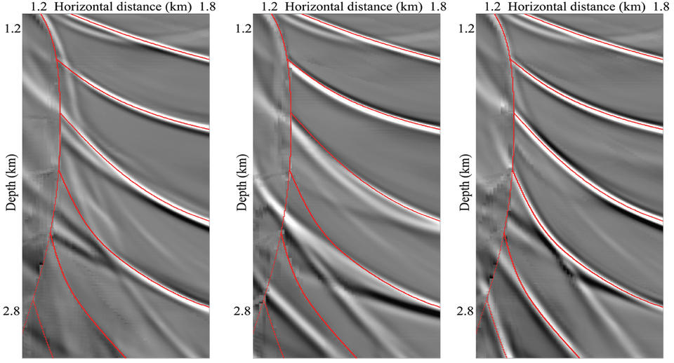
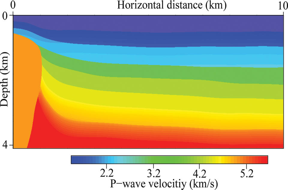
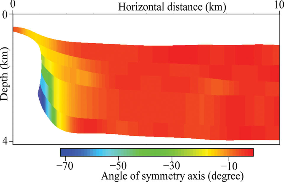
An example of a salt structure with several adjacent transversely isotropic shale layers where the axis of symmetry is normal to the bedding (the two top pictures). Depth migrated images are shown (from left to right) using an isotropic model, a VTI model and the TTI model. It can be seen that a good subsurface image in the vicinity of the salt dome is obtained only when using the TTI model. The VTI model shows a misfit for the lower reflectors whereas the isotropic model images them poorly.